
Gentle introduction to geospatial concepts
Introduction
Section titled “Introduction”This module provides an introduction to fundamental GIS concepts, including coordinate reference systems, map projections, and raster and vector data models. By completing this module, you will gain a clear understanding of these concepts and their importance in geospatial applications.
By the end of the module, you should know: different applications of GIS; what coordinate reference systems and map projections are and their importance; what are raster and vector geospatial data.
What you should already know
Section titled “What you should already know”Since this is a beginner module, no previous knowledge of GIS or QGIS is required.
Spatial data models
Section titled “Spatial data models”In GIS, everything is a layer, which is a way of representing a particular type of geospatial data.
Spatial data models are composed of two primary components that, when combined, model reality. These components are:
- spatial features (geometry)
- attributes
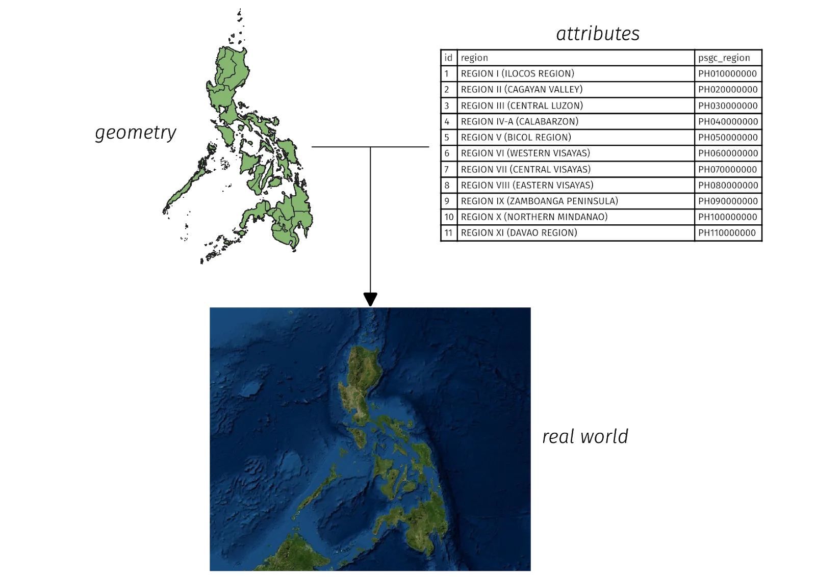
There are two main spatial data models: raster and vector. Although any real-world object can be represented by either data model, one data model is usually better at representing certain real-world objects than the other.
Raster data
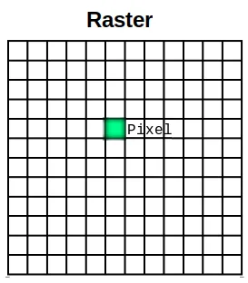
Section titled “Raster data”A raster is a cell-based or pixel-based representation of real-world objects composed of rows and columns of cells or pixels where each cell or pixel represents a geographical area (think of a photograph or an image). The value of the cell represents the value of an attribute in the said geographic area. The size of the area is dependent on the spatial resolution of the raster.
Rasters are particularly useful for representing continuous phenomena, such as elevation or precipitation, due to their composition of a matrix of contiguous cells, where each cell or pixel contains a single numeric value. They are also are quite useful for site suitability modelling since you can combine rasters via mathematical operations (raster algebra).
Vector data
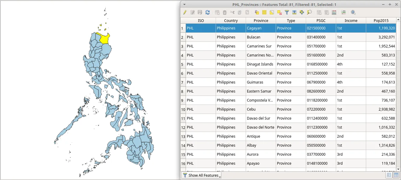
Section titled “Vector data”Vector data comes in three primary forms: point, line, and polygon. It is more precise than rasters because points, lines, and polygons are modelled using well-defined coordinates thus making them better at representing discrete objects than rasters.
Vectors are commonly used when precise lengths, areas, and distances are needed. They are also useful when performing network analysis (e.g. finding the shortest path of road from one point to another).
Spatial databases
Section titled “Spatial databases”Although not technically a spatial data type, a spatial database also deserves attention when talking about spatial data. A spatial database, as its name suggests, is a database that has spatial attributes (or geometry). Spatial databases allow for both vector and raster data to be stored in a single place. Aside from this, some spatial databases allow for queries to be performed on them without the need of a GIS. Some examples of spatial databases are:
- Postgres with PostGIS extension
- GeoPackage (SQLite with spatial extension)
Types of data you might encounter in geospatial
Section titled “Types of data you might encounter in geospatial”The types of data and example file formats that you might encounter when working in the geospatial field include:
- Rasters (.tiff, .img, .png)
- Vectors (geopackage, geojson, shapefile)
- Tiles (vector tiles, raster tiles)
- Databases (PostGIS, GeoPackage)
- Web services (WMS, WFS, WMTS)
- Point Clouds (.LAZ, .LAS)
- Mesh Data (netCDF)
These data types and file formats are discussed further in more advanced courses/workbooks.
A quick note about shapefiles and where to find free and open geospatial data
Section titled “A quick note about shapefiles and where to find free and open geospatial data”Most people who are new to GIS usually get introduced to spatial data via shapefiles. Unfortunately, most people never outgrow this and use shapefile to mean all types and forms of spatial data. This is similar to using COLGATE to mean toothpaste or COKE to mean soft drinks. A shapefile is a file format for vector data. As such, all shapefiles are vector data but not all vector data are shapefiles: again, all COKE drinks may be soft drinks but not all soft drinks are COKE. This isn’t wrong per se but it’s rather unfortunate since there are other vector data formats that are more appropriate than shapefiles for some use cases. Examples of these are:
- GeoPackage (.gpkg),
- GeoJSON (.geojson) and TopoJSON (.json),
- Vector tiles (.mbtiles)
- flatgeobuf, and more recently
- GeoParquet
Now, the shapefile format is mostly an open format—its specification is published although it was not developed in an open forum. The format, while ubiquitous, has some significant limitations such as:
- It is not just 1 file. A shapefile actually consists of several files, 3 of which are mandatory: .shp, .shx, .dbf. All other files are called sidecar files.
- It has a 2GB size limit for each individual file.
- Field names are limited to 10 characters.
- Attribute columns are limited to 255 columns.
- There is no support for some data types such as time.
- It does not explicitly store topology.
Other data formats such as GeoPackage, GeoJSON, TopoJSON, and flatgeobuff remedy these limitations of shapefiles. In fact, QGIS and GRASS GIS have switched to GeoPackage as the default vector file format when importing or exporting layers and although GeoPackage also has some limitations, especially in terms of concurrent usage, being a completely open format allows the community to help shape the future of the format.
Vector tiles have made using vector data on web applications much easier while specifications such as GeoParquet and GeoArrow are built for more big data and cloud data warehousing applications.
So, if not shapefiles, what should you use?
There’s nothing wrong with using shapefiles especially if it fits your use-case. If you don’t need a dataset that goes beyond 2GB; if you’re okay with having a limit of 10 characters to your field names; or if you’re working with a small number of files locally, a shapefile is completely fine . However, if you want to package your QGIS project together with all the layers (vectors, rasters), styling, and models; or you want to share multiple types of layers and spatial data in a single file, a GeoPackage is worth a look. GeoPackages and GeoJSONs are also web-friendly and can be used directly by web mapping libraries such as Mapbox and Leaflet.
You can read more in the link below: https://bnhr.xyz/2018/12/12/i-choose-geopackage.html
Map projections or why all maps lie
Section titled “Map projections or why all maps lie”When you think of planet Earth, what do you usually picture? For most of us (unless we’re flat-earthers), it’s probably the spherical mass of blue, green, white, and brown floating in space.
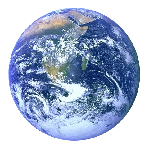
The earth is in the shape of a sphere or an oblate spheroid if you want to be technical about it—a geoid if you want to be overly technical. This is why the traditional way to model the earth is through the use of globes.
However, even though the globe is able to capture most of the characteristics of the earth, it suffers from two main drawbacks:
- Globes are cumbersome and difficult to bring with you. Imagine having to carry a globe around for navigation. In a world of web maps and navigation apps, this idea seems preposterous.
- Globes are only usable at small scales (e.g. finding locations of countries). They are next to useless for activities that require large scales or fine details (e.g. city navigation). Imagine having to use a globe to navigate Metro Manila. The globe would probably have to be the size of a hot air balloon just so you’d be able to see the streets of Metro Manila on it.
This is where maps come in.
Maps remedy these two drawbacks of globes by representing the earth as a flat surface. By doing so, maps become portable and suitable for a multitude of uses. Having said that, maps also introduce a drawback of their own. Through the process of converting a three-dimensional object (globe) into a two-dimensional one (map), distortions are introduced such that it is impossible for a map to perfectly capture the different characteristics of the earth (i.e. shapes, areas, directions).
All maps lie. Or better yet, all maps are unable to tell the whole truth.
Map projections are used to flatten the earth’s (or globe’s) surface into a plane in order to create a map. In other words, a map projection transforms the three-dimensional figure of the earth into a two-dimensional one.
As previously mentioned, this transformation process introduces distortion. If you look at the photo of the orange to the right, you’ll notice that the figure created by peeling the fruit is not perfectly flat. If you try to make the orange perfectly flat, you’ll encounter the following issues:
- Shearing - the lengthening of the skin (or surface) in one or more directions
- Tearing - the splitting or breaking apart of the skin (or surface)
- Compressing - the shortening or shrinking of the skin (or surface)
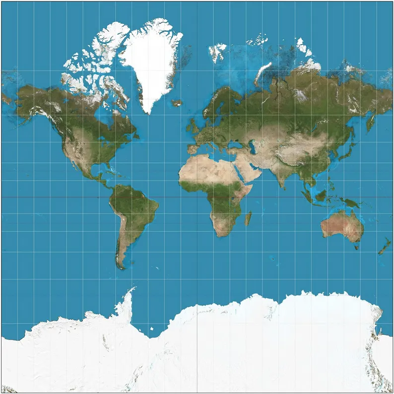
Pictured above is a map of the world made with the Mercator projection, one of the most popular map projections and the one commonly used in world maps.
As you might have read or heard before, this map that you’ve seen all your life is wrong!
In its defense, all maps are, in one way or another, wrong.
Because of this, each map created contains distortion in one or more of the following characteristics:
- Shape
- Area
- Distance
- Direction
Map projections can preserve (no distortion) one or more characteristics but never all at the same time. Alternatively, they can have a compromise where the distortions are balanced and minimized for all characteristics. This is due to the nature of the characteristics themselves.
Major characteristics like Shape and Area are mutually exclusive and cannot be preserved simultaneously. Meanwhile, the minor characteristics, Distance and Direction can be preserved but not everywhere on the map.
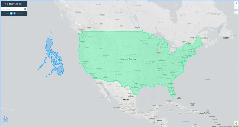
In choosing what map projection to use, it’s important that you consider the purpose of the map. For example, if you wish to perform area-based analyses, it’s best to use a map projection that preserves the area.
If you’re curious to know the actual relative sizes of the countries of the world, feel free to check out https://thetruesize.com/ as shown below. 😊
Classifications of map projections
Section titled “Classifications of map projections”Distortion
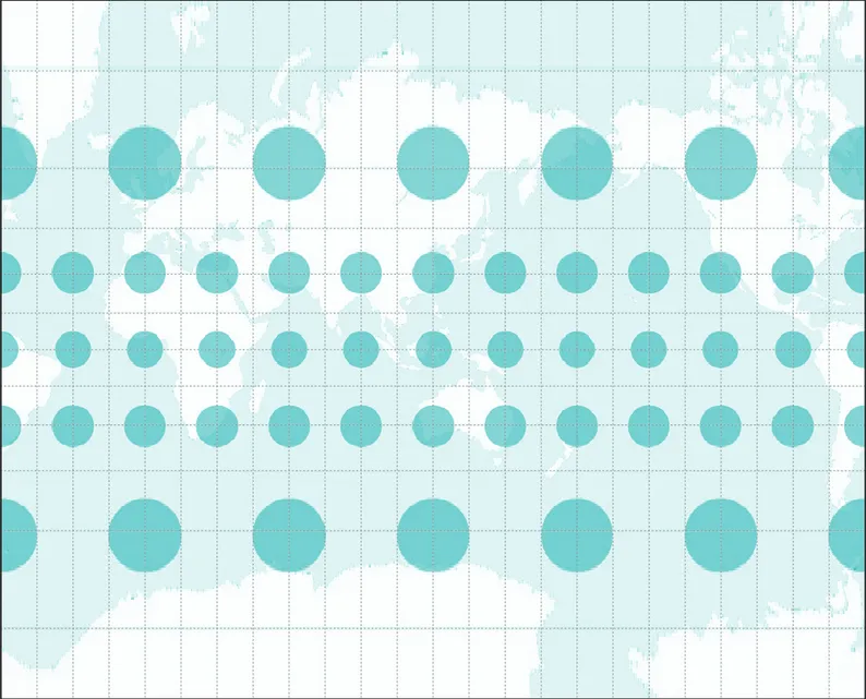
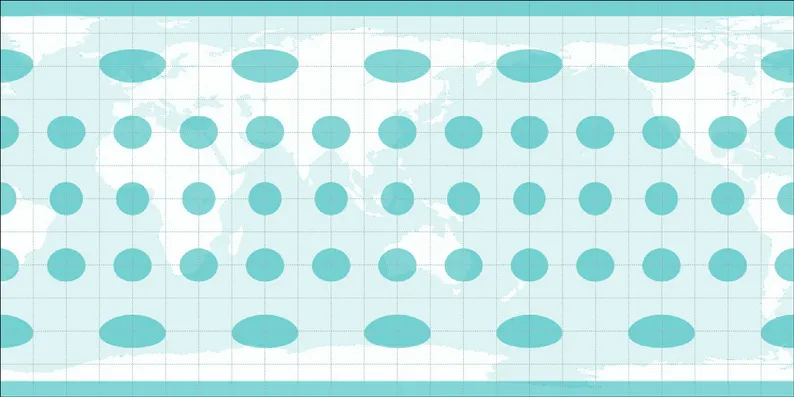
Section titled “Distortion”There are several ways to classify map projections. The first one is based on the characteristic that they preserve. One way to show this is by what’s called the Tissot’s indicatrix. This indicator characterizes local distortions by using circles and showing how these circles are transformed over the map.
Conformal or Orthomorphic map projections are those that preserve shape or angular conformity. These are commonly used in maps for navigation or meteorological purposes. Shapes are preserved but areas are distorted. The larger the area, the greater the distortion (Figure 7).
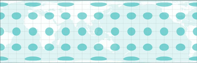
Equal-area or Authalic map projections are those that preserve the proportion or relative areas of the objects in the map. In this kind of map projection, the larger the area being mapped, the more precise it is (Figure 8).
Equidistant map projections preserve the distance of lines originating from one or two points on the map or have proper scale along one or more lines (Figure 9).
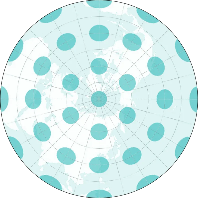
Azimuthal map projections preserve the direction from one or two points on the map. These are useful for mapping routes of aircrafts and seacrafts between ports (Figure 10).
A single map projection can preserve more than one characteristic (e.g. an Azimuthal Equidistant projection that preserves the direction and distances from one or two points on the map) but not all of them.
Aside from being functional, maps are also created to be aesthetically pleasing. Map-making is a science and an art.
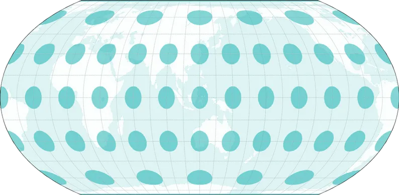
A few years ago, a new equal-area map projection called Equal Earth (Figure 11) was developed to create a general purpose map projection that’s both functional and pleasing to the eyes.
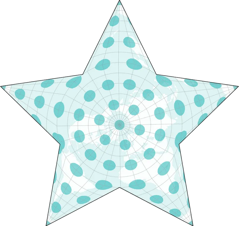
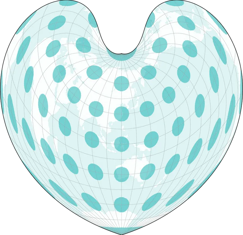
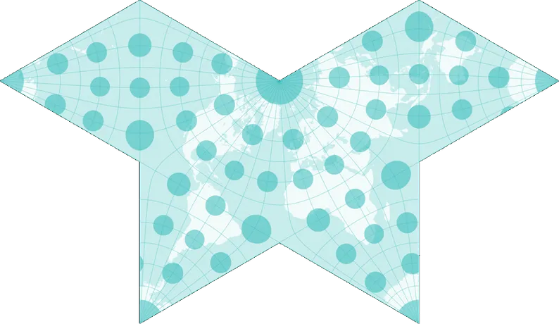
Meanwhile, some map projections can be considered as pieces of art by themselves. The Berghaus projection results in an azimuthal equidistant aphylactic map in the shape of a star (Figure 12). The Bonne projection creates an equal-area map in the shape of a heart (Figure 13). Meanwhile, the Cahill projection results in butterfly-shaped maps (Figure 14). Whoever said that cartographers aren’t the romantic-type?
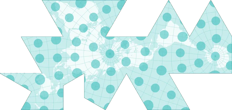
The Dymaxion (Figure 15 or Fuller map named after its creator Buckminster Fuller projects the globe into an icosahedron instead of other common surfaces like the cylinder or cone. This results in a highly interrupted (or split) map but also enables the map to show all the continents as an interconnected land mass or “one island” which, as others may say, highlights the “one-ness” of the human race.
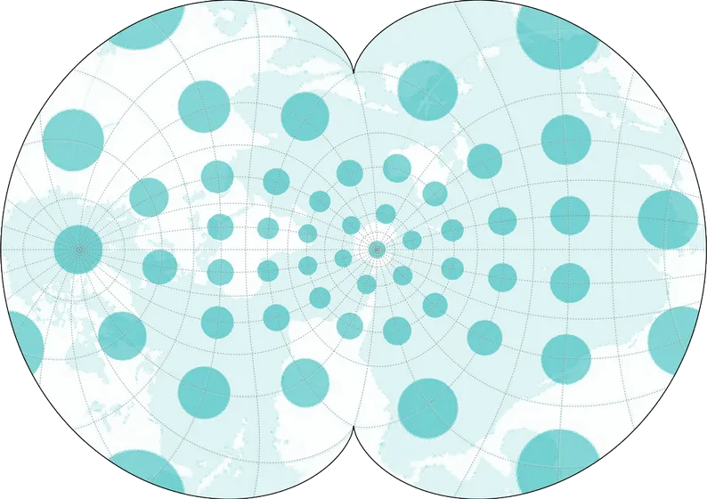
At the other end of the spectrum is the Spillhaus (Figure 16) projection which shows all the world’s oceans as one body of water—perfect for water-lovers.
Developable Surface
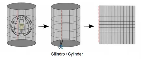
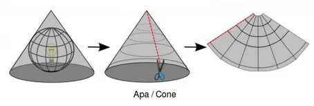
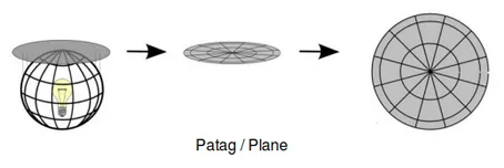
Section titled “Developable Surface”Another way to classify map projection is by the developable surface used to create the map. A surface is developable if it can be flattened without introducing distortions. The most commonly used surfaces are: Cylinders (Figure 17), Cones (Figure 18), and Planes (Figure 19).
There are countless developable surfaces that can be used to transform a globe into a map. They can be a variation of the common surfaces like in the case of pseudo-cylindrical and pseudo-conic projections or they can be unique and entirely different surfaces such as in the Dymaxion map which uses a icosahedron (polyhedron with 20 faces), or the Cahill-Keyes projection which uses an octahedron (polyhedron with 8 faces).
Aspect
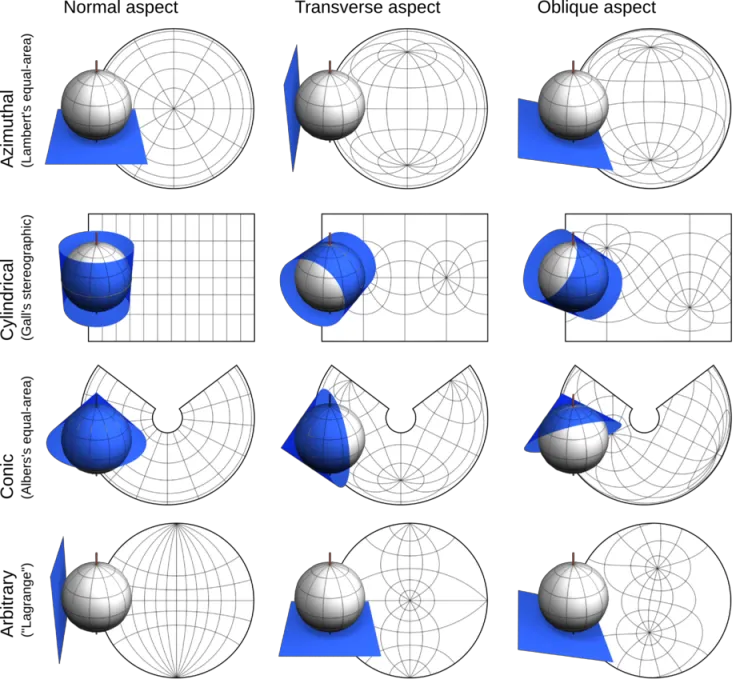
Section titled “Aspect”A map projection can also be classified according to its aspect (Figure 20) or how the developable surface is positioned on the globe: either Normal, Transverse, or Oblique.
Coordinate reference systems (CRS) or how we define here
Section titled “Coordinate reference systems (CRS) or how we define here”A Coordinate Reference System (CRS) is used to specify the location of an object on the surface of the earth through the use of coordinates.
Coordinate reference systems can be classified into two:
- Geographic Coordinate Reference Systems use degrees of latitude and longitude as coordinates to refer to position.
- Projected Coordinate Reference Systems use linear units (e.g. meters, feet, kilometers) of eastings and northings as coordinates.
There are other coordinate reference systems out there but these are the “classic” or “conventional” ones. Can you name some unconventional coordinate or geocode systems?
Knowledge of coordinate reference systems is important because even if two maps (or layers) show the same area, the coordinates of the locations in those maps will be different if the CRS they use are different.
Take this example: Map A and Map B show the same area and extent. They’re basically the same map. The only difference is the coordinate reference system they use. Map A uses CRS X and Map B uses CRS Y. Let’s say we get the coordinate of Point 1, which is (10, 10), from Map A. If we look at the coordinate (10,10) in Map B, it’s possible that Point 1 won’t be there since Map B uses a different CRS. Or if you overlay the maps over each other using a common reference, the features on the two maps won’t coincide. This knowledge of coordinate reference systems is important in any GIS.
Prior to QGIS 3.X, QGIS had an option to activate what’s called “OTF” or “On-The-Fly Transformation”. This allows layers with different CRS to be projected on the map canvas as if they were in the same CRS. With QGIS 3.X onward, this option is the default behavior of QGIS.
QGIS also performs this action automatically for processing tasks. This is very important because if the layers aren’t in the same CRS, the results of spatial queries and processing like spatial joins, clips, etc. could be compromised.
You may notice that some Coordinate Reference Systems are referred to by their EPSG Code (EPSG = European Petroleum Survey Group). This code refers to the CRS’ code in the EPSG Geodetic Parameter Dataset which is a registry of geodetic datums, spatial reference systems, Earth ellipsoids, coordinate transformations and related units of measurement. Most GIS, including QGIS, refer to the EPSG code to identify coordinate reference systems, projections, and perform transformations between these systems.
Common EPSG Codes include:
- EPSG:4326 - WGS 84, latitude/longitude coordinate system based used by the Global Positioning System (GPS) among others.
- EPSG:3857 - Web Mercator projection used for display by many web-based mapping tools such as OpenStreetMap and Google Maps
- EPSG:32650 to EPSG 32653 - Universal Transverse Mercator (UTM) Zone 50N to 53N. UTM zones used in the Philippines
- EPSG:4683 - Philippine Reference System of 1992
Quiz and discussion questions
Section titled “Quiz and discussion questions”INTRODUCTION TO GIS
-
GIS such as QGIS can only be used with geospatial data.
a. TRUE
b. FALSE
-
A map is always the output when using GIS.
a. TRUE
b. FALSE
-
Learning GIS is always difficult and expensive.
a. TRUE
b. FALSE
SPATIAL DATA TYPES
-
You want to map roads and streets in order to find the service area of hospitals in an area. What data type is best to use to represent these roads and streets?
a. Raster
b. Vector
c. Both can be used equally well
-
You want to show the continuous elevation in an area. What data type is best to use for this purpose?
a. Raster
b. Vector
c. Both can be used equally well
-
You used a drone to collect drone imagery. What data type is this imagery in?
a. Raster
b. Vector
MAP PROJECTIONS AND COORDINATE REFERENCE SYSTEMS
-
It is possible to preserve both area and shape together in a single map.
a. TRUE
b. FALSE
-
It is possible to preserve both distance and direction together in a single map.
a. TRUE
b. FALSE
-
What type of map projection is best for a map showing a comparison of a 10-km buffer zone centered at different locations?
a. Conformal
b. Equidistant
c. Equal area
-
What type (geographic or projected) of coordinate reference system is preferred to use for showing the location of points using GPS?
a. Geographic CRS
b. Projected CRS
-
What type (geographic or projected) of coordinate reference system is preferred to use for computing the distance between two points?
a. Geographic CRS
b. Projected CRS
Certification and support
Section titled “Certification and support”Contact us or sign-up to our courses if you are interested in having this as an instructor-led or self-paced course.