
Preparing the area data
Before we begin
Section titled “Before we begin”What we want to achieve
Section titled “What we want to achieve”- Create the area corners (point) and area boundary (polygon) shapefiles with the prescribed attributes.
- Plot the application area from a technical description, from a list of corner coordinates, and from an existing layer.
- Validate the geometry of the application area.
- Fill in the attributes following the guide’s rules.
What we have
Section titled “What we have”- bnhr_qgis-sflma-mapping-001.gpkg that contains:
- sample_td - the technical description (bearings and distances) of the sample application
- sample_tie_point - the reference point (tie point) of the sample technical description, with its coordinates and the tie line as given in the technical description (given_bearing, given_distance)
- sample_invalid - a polygon with geometry errors, for the validity exercise
- ref_barangays, ref_municipalities, and ref_provinces - reference administrative boundaries
- sample_corners.csv - the corner coordinates of the sample application
- sample_td_tie-line.txt and sample_td_boundary.txt - the sample technical description as input files for the Azimuth and Distance plugin
Relevant QGIS knowledge/skills
Section titled “Relevant QGIS knowledge/skills”- Creating a new vector layer
- Digitizing settings and snapping
- Mapping tracts of land from technical descriptions
- Loading delimited text files
- Field calculator
- Expressions
The prescribed shapefiles
Section titled “The prescribed shapefiles”The guide requires two shapefiles: the tenure corners as a point layer and the tenure boundary as a polygon layer.
Area corners (point)
Section titled “Area corners (point)”| Field name | Data type | Description |
|---|---|---|
| T_CORNER | Short Integer | Precision: 0 |
| NORTHINGS | Double | Northing (Y) coordinate of the point in meters. Precision: 0 |
| EASTINGS | Double | Easting (X) coordinate of the point in meters. Precision: 0 |
| X | Double | Precision: 0. Must be left blank |
| Y | Double | Precision: 0. Must be left blank |
| NAME | Text | Name of applicant, do not abbreviate. Length: 255 |
| TENURE | Text | Name of tenure, do not abbreviate |
| REGION | Text | Region, in Roman numerals. Length: 50 |
| PROVINCE | Text | Province, do not abbreviate. Length: 255 |
| MUNI_CTY | Text | Municipality/City, do not abbreviate. If two or more, alphabetize and use only a comma as separator. Length: 255 |
| BARANGAY | Text | Barangay, do not abbreviate. If two or more, alphabetize and use only a comma as separator. Length: 255 |
Area boundary (polygon)
Section titled “Area boundary (polygon)”| Field name | Data type | Remarks |
|---|---|---|
| AREA | Text | In hectares. Precision: 0 |
| NAME | Text | Name of applicant, do not abbreviate. Length: 255 |
| TENURE | Text | Name of tenure, do not abbreviate |
| REGION | Text | Region, in Roman numerals. Length: 50 |
| PROVINCE | Text | Province, do not abbreviate. Length: 255 |
| MUNI_CTY | Text | Municipality/City, do not abbreviate. If two or more, alphabetize and use only a comma as separator. Length: 255 |
| BARANGAY | Text | Barangay, do not abbreviate. If two or more, alphabetize and use only a comma as separator. Length: 255 |
Translating the prescribed types to QGIS
Section titled “Translating the prescribed types to QGIS”The guide’s data types use ArcGIS names. In the New Shapefile Layer dialog of QGIS they are:
| Guide | QGIS type | Length | Precision |
|---|---|---|---|
| Short Integer | Integer (32 bit) | 4 | |
| Double | Decimal (double) | 20 | 3 |
| Text, length 255 | Text (string) | 254 | |
| Text, length 50 | Text (string) | 50 |
2.1. Creating the area corners and area boundary shapefiles
Section titled “2.1. Creating the area corners and area boundary shapefiles”What we want to achieve
Section titled “What we want to achieve”- Two empty shapefiles, one point and one polygon, with the prescribed fields and in the CRS of the technical description, named in the prescribed format.
- Open Layer ‣ Create Layer ‣ New Shapefile Layer….
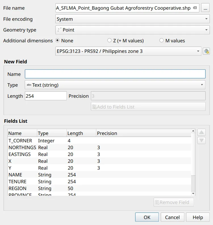
- Create the point shapefile for the area corners:
- File name:
IV-A_SFLMA_Point_Bagong Gubat Agroforestry Cooperative.shp - Geometry type: Point
- CRS: EPSG:3123 - PRS92 / Philippines zone 3
- Remove the default id field from the Fields List.
- Add each field in the area corners table using the QGIS types: type the Name, choose the Type, set the Length and Precision, then click Add to Fields List.
- File name:
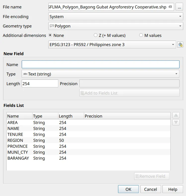
- Create the polygon shapefile for the area boundary in the same way, named
IV-A_SFLMA_Polygon_Bagong Gubat Agroforestry Cooperative.shp, with the fields in the area boundary table.
- In the Layers panel, rename the two layers area_corners and area_boundary. The expressions and the layout template in this course refer to the layers by these names.
Plotting the application area
Section titled “Plotting the application area”How you plot the area depends on what the applicant provides. All three methods end in the same place: a closed polygon in the area boundary shapefile, in the correct CRS.
2.2. Plotting the area from a technical description
Section titled “2.2. Plotting the area from a technical description”What we want to achieve
Section titled “What we want to achieve”- The boundary of the sample application plotted from its bearings and distances, starting from the tie point.
What we have
Section titled “What we have”- sample_td_tie-line.txt - the tie point’s coordinates and the tie line, as input for the Azimuth and Distance plugin
- sample_td_boundary.txt - the nine lines of the technical description, from corner 1 back to corner 1
Review Mapping land parcels with the Azimuth and Distance plugin if you have not used the plugin before. The input files look like this:
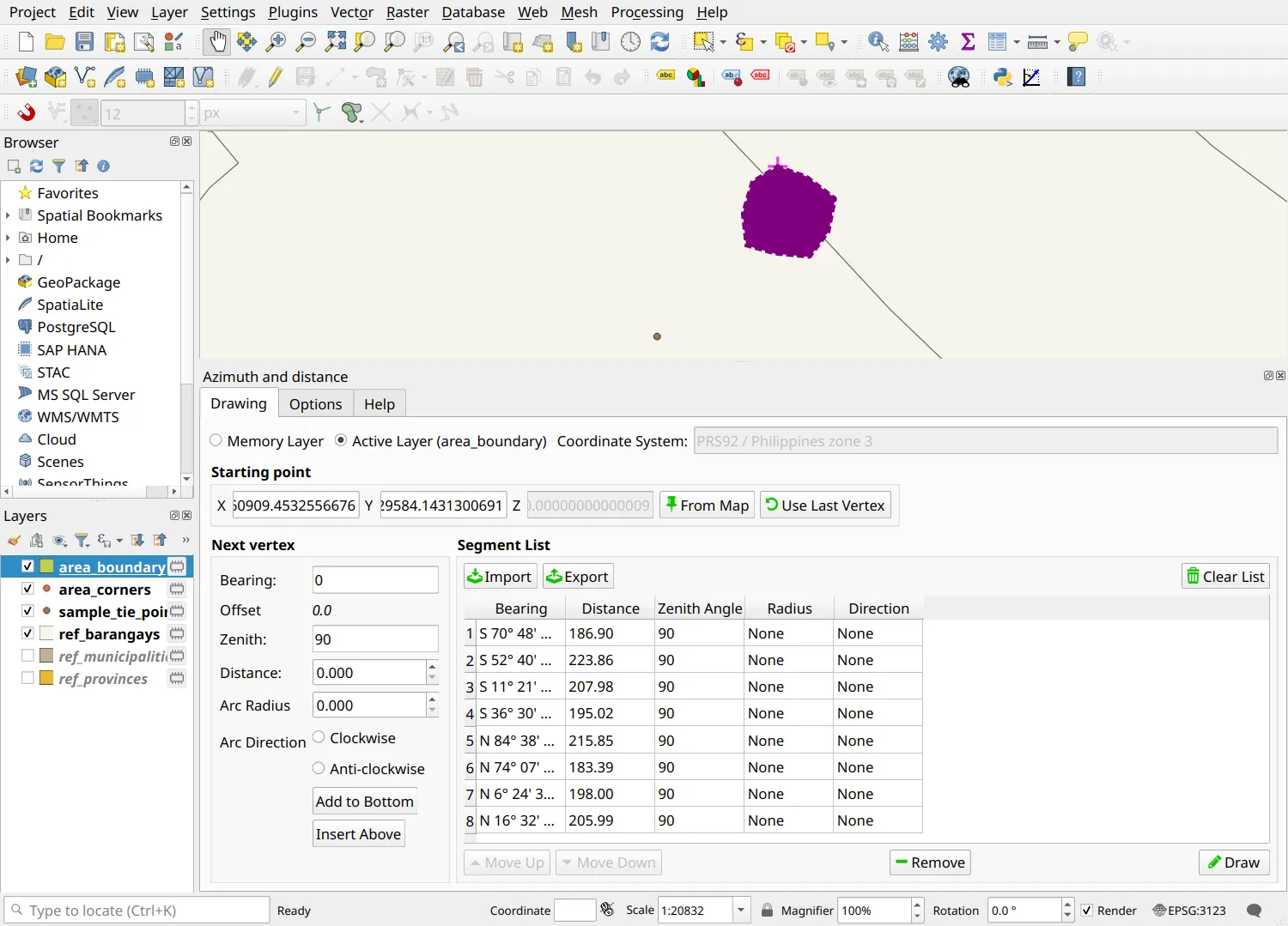
angle=Bearingheading=Coordinate_Systemdist_units=Defaultangle_unit=degreesurvey=Polygonal[data]S 70° 48' 03" E;186.90;90S 52° 40' 51" E;223.86;90...N 59° 19' 00" E;182.83;90- Open the plugin (Plugins ‣ Topography ‣ Azimuth and distance). In the Drawing tab, click Import and open sample_td_tie-line.txt. The starting point becomes the tie point, and the tie line runs to corner 1.
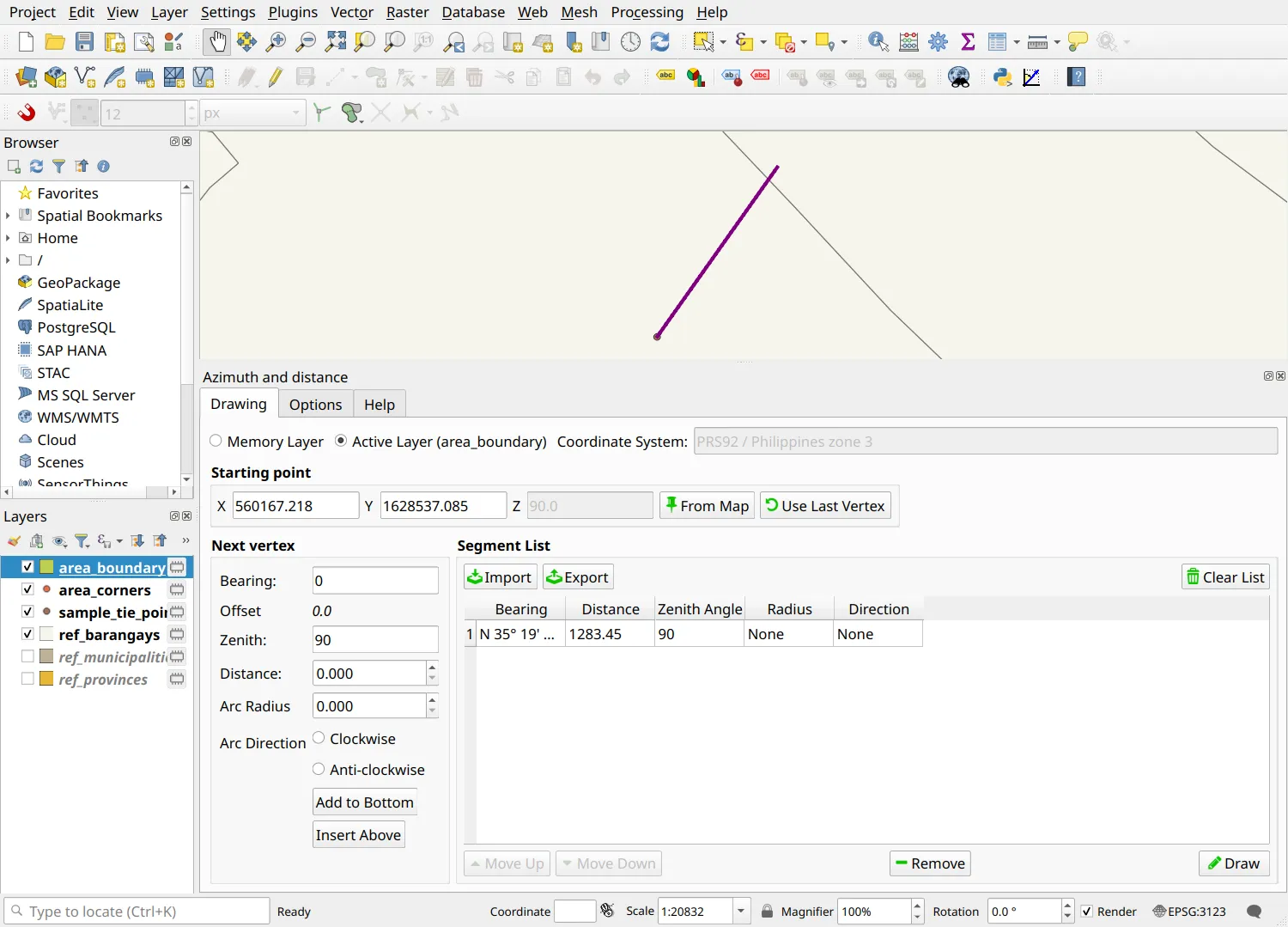
- Click Use Last Vertex. The starting point moves to the end of the tie line: corner 1.
- Click Import again and open sample_td_boundary.txt. The preview shows the nine lines of the boundary.
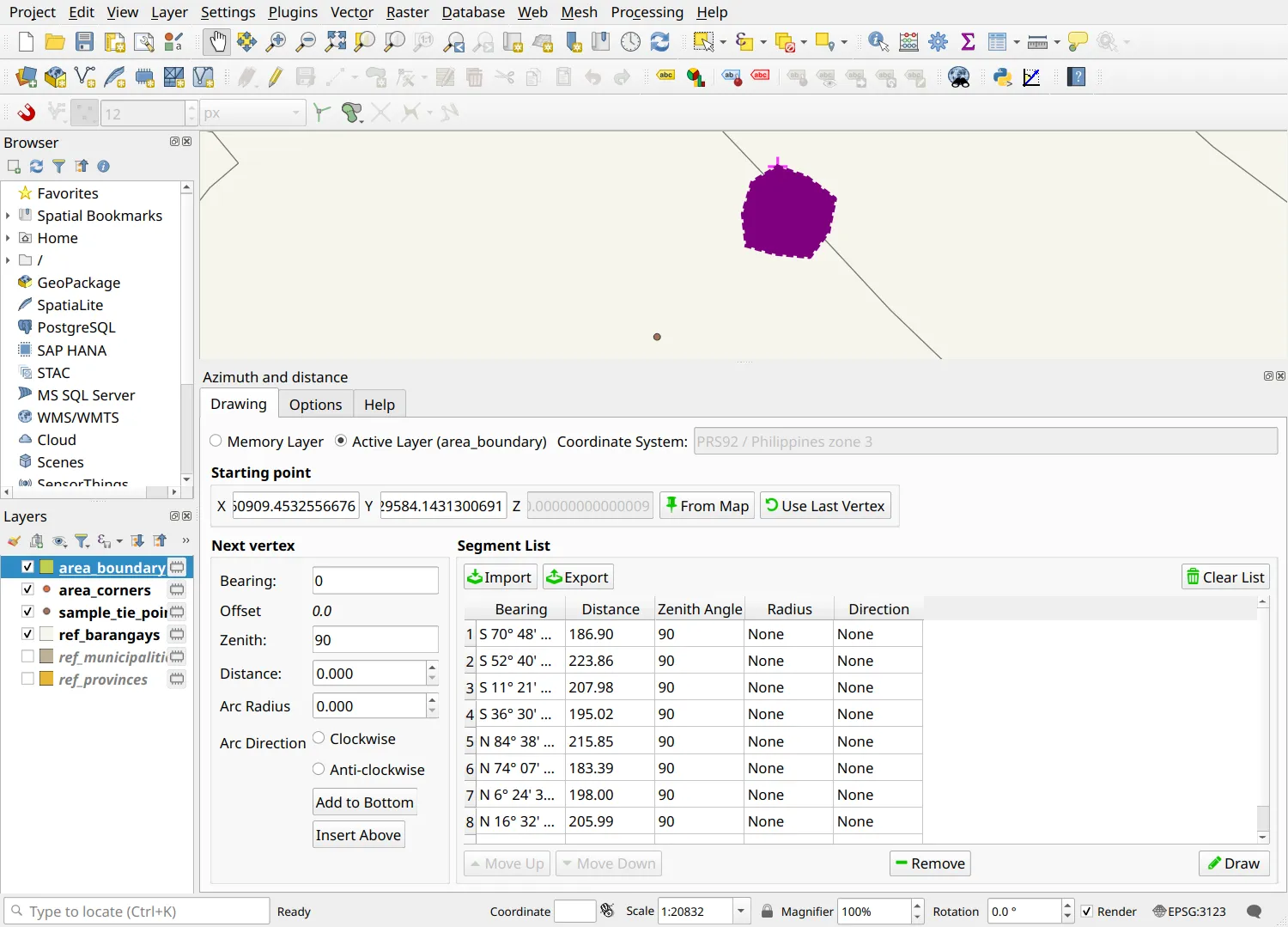
- Select the last line (9-1) in the Segment List and click Remove. A polygon closes itself back to its first point, so keeping the closing line would add a tenth corner 4.9 mm away from corner 1.
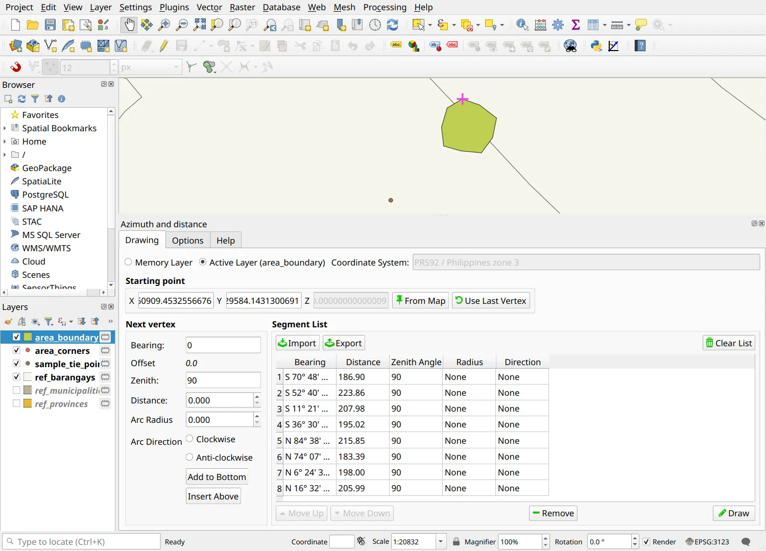
- Select area_boundary in the Layers panel, choose Active Layer in the plugin, and click Draw.
- Save your edits (
 ). The area boundary now has exactly nine corners.
2.3. Plotting the area from a list of corner coordinates
Section titled “2.3. Plotting the area from a list of corner coordinates”What we want to achieve
Section titled “What we want to achieve”- The boundary of the sample application created from a CSV of corner coordinates.
What we have
Section titled “What we have”- sample_corners.csv - the corner numbers, eastings, and northings of the sample application
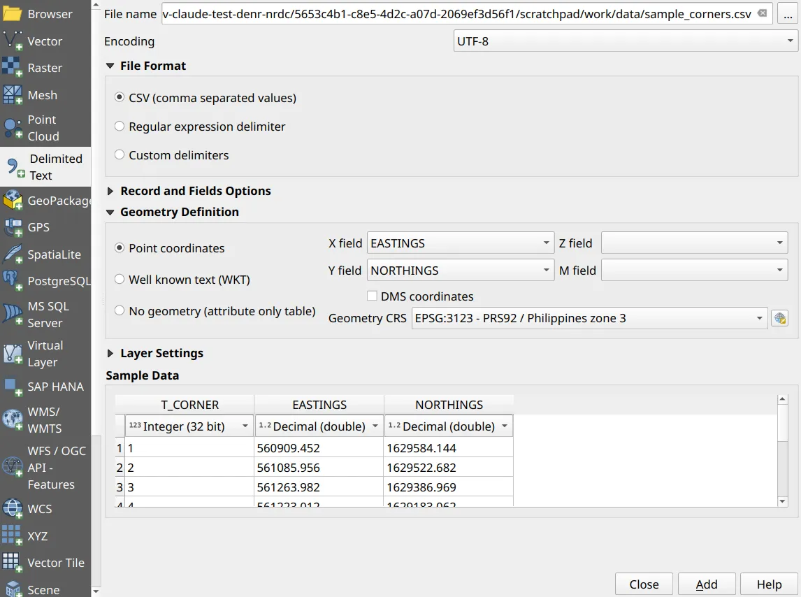
- Open Layer ‣ Add Layer ‣ Add Delimited Text Layer… and choose sample_corners.csv. Under Geometry Definition, choose Point coordinates, set X field to EASTINGS and Y field to NORTHINGS, and set the Geometry CRS to EPSG:3123.
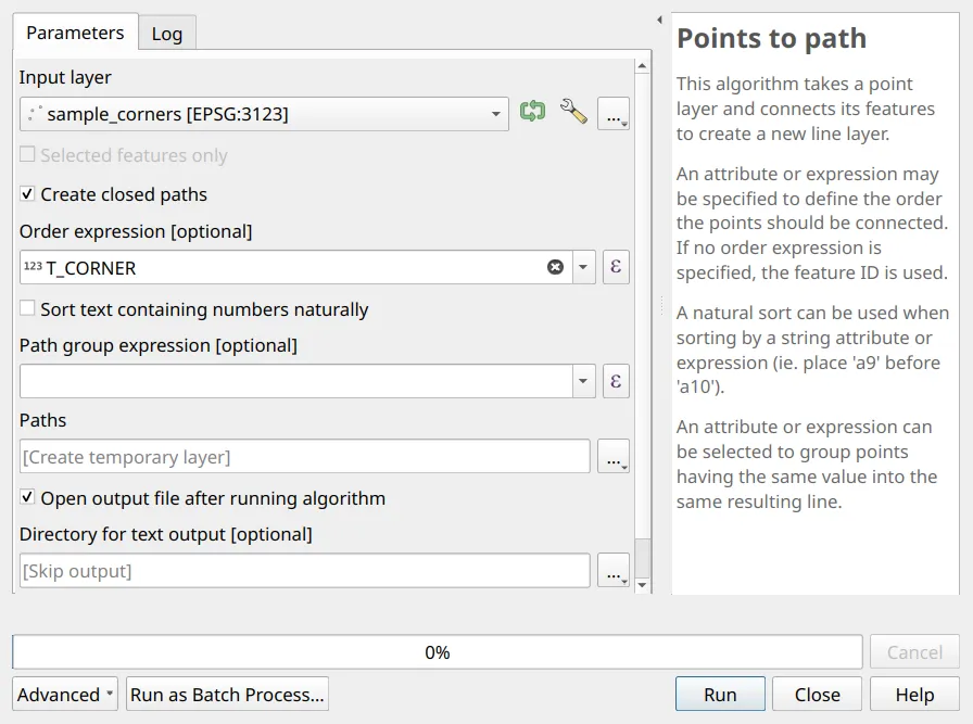
- Connect the corners in order with Processing Toolbox ‣ Points to path: check Create closed paths and set the Order expression to T_CORNER.
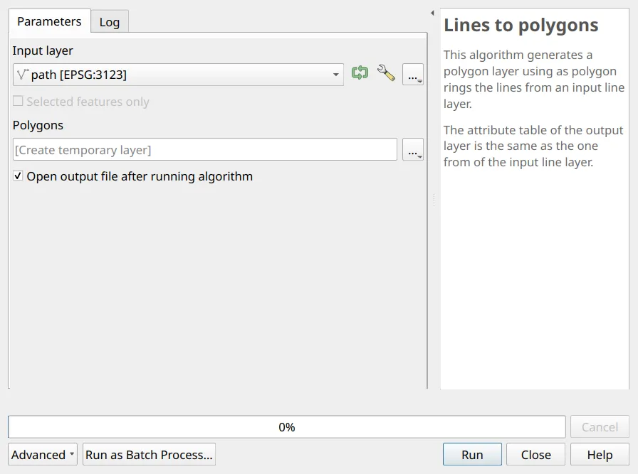
- Convert the path into a polygon with Processing Toolbox ‣ Lines to polygons.
- Copy the polygon (Edit ‣ Copy Features) and paste it into the area boundary shapefile (Edit ‣ Paste Features).
2.4. Preparing the area from an existing layer
Section titled “2.4. Preparing the area from an existing layer”What we want to achieve
Section titled “What we want to achieve”- An application area digitized or edited against reference layers, with clean, snapped vertices.
- Enable snapping in the Snapping Toolbar: snap to vertices and segments of all layers, with a tolerance of about 12 pixels.

- Toggle editing on the area boundary shapefile and digitize the area with the Add Polygon Feature tool (
 ), tracing shared boundaries where appropriate.
 - Use the Advanced Digitizing Panel to enter exact bearings and distances where the boundary follows a surveyed line.
- Save your edits ().
Validating the geometry
Section titled “Validating the geometry”An invalid polygon gives a wrong area and a wrong technical description, so validation comes before any computation.
2.5. Checking and fixing the application area
Section titled “2.5. Checking and fixing the application area”What we have
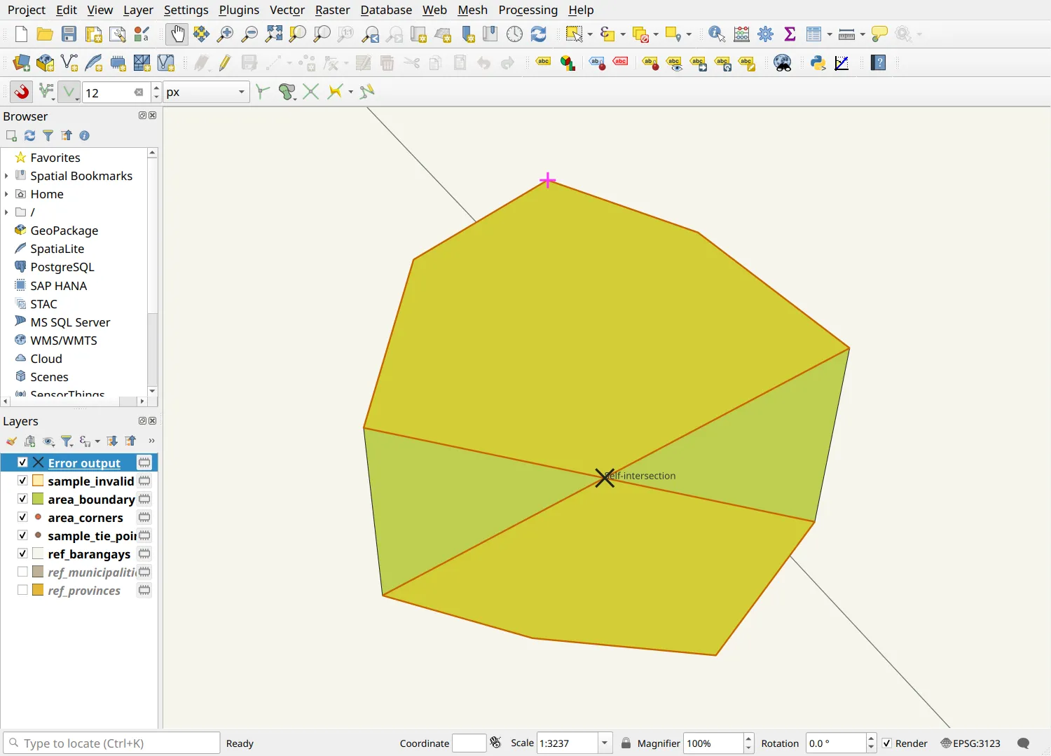
Section titled “What we have”- sample_invalid - the sample boundary with two corners swapped (so the boundary crosses itself) and one corner entered twice
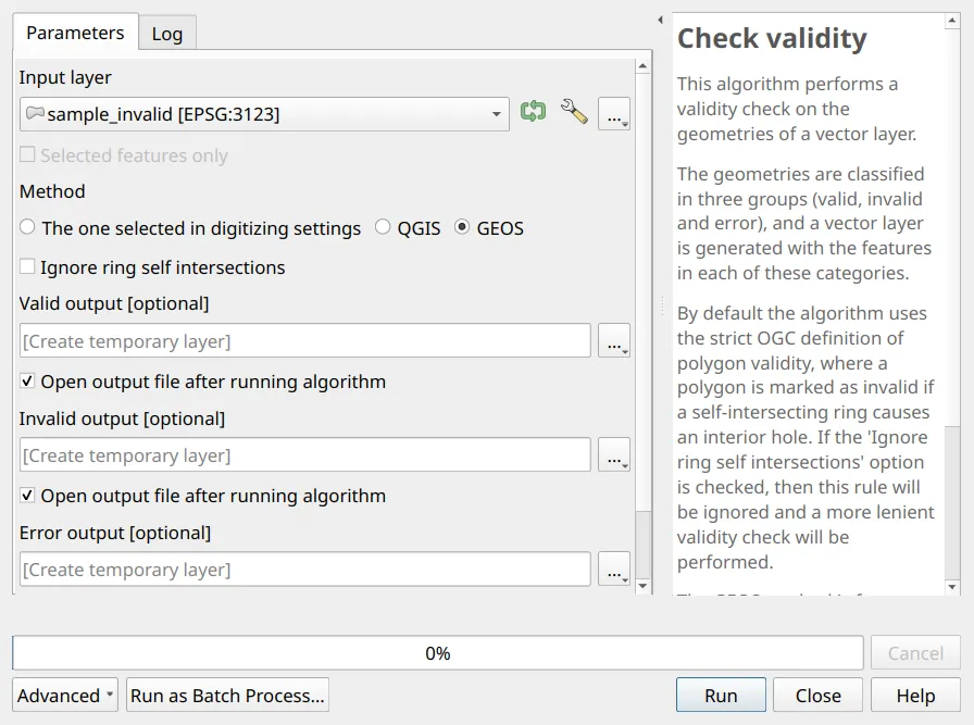
- Run Processing Toolbox ‣ Check validity on sample_invalid with the GEOS method.
- The Error output layer marks where the boundary crosses itself.
- Fix the error with the Vertex Tool by moving the swapped corners back into order, and delete the repeated corner. Run Check validity again until the polygon is valid.
- Check that the polygon has the same number of corners as the technical description.
Filling in the attributes
Section titled “Filling in the attributes”Rules for attribute values
Section titled “Rules for attribute values”- Do not abbreviate names of the applicant, tenure, province, municipality/city, or barangay.
- Write the region in Roman numerals.
- If the area covers two or more municipalities/cities or barangays, list them alphabetically, separated only by a comma.
- Leave X and Y blank in the area corners shapefile.
2.6. Computing the area and location attributes
Section titled “2.6. Computing the area and location attributes”What we want to achieve
Section titled “What we want to achieve”- A filled-in area boundary attribute table, with AREA computed in hectares and the location fields derived from the reference layers.
- Open the Field Calculator (
 ) on area_boundary, check Update existing field, choose AREA, and enter:
format_number(area($geometry) / 10000, 4, omit_group_separators:=true)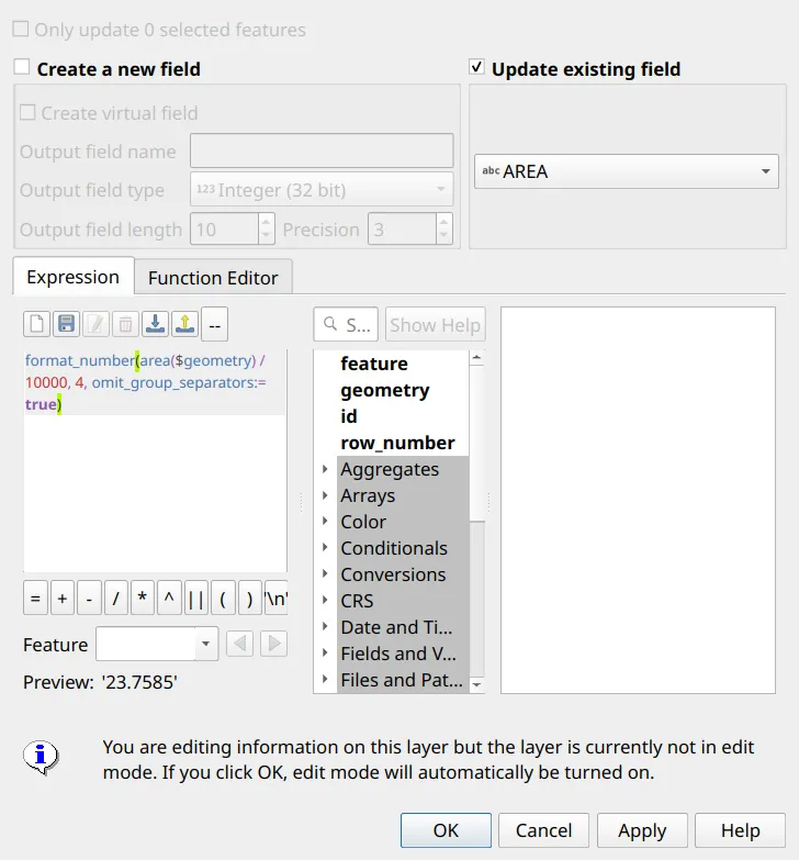
- Update BARANGAY with the barangays the polygon overlaps, sorted alphabetically and joined with a comma:
array_to_string(array_sort(array_distinct(overlay_intersects('ref_barangays', "barangay", min_overlap:=1))), ',')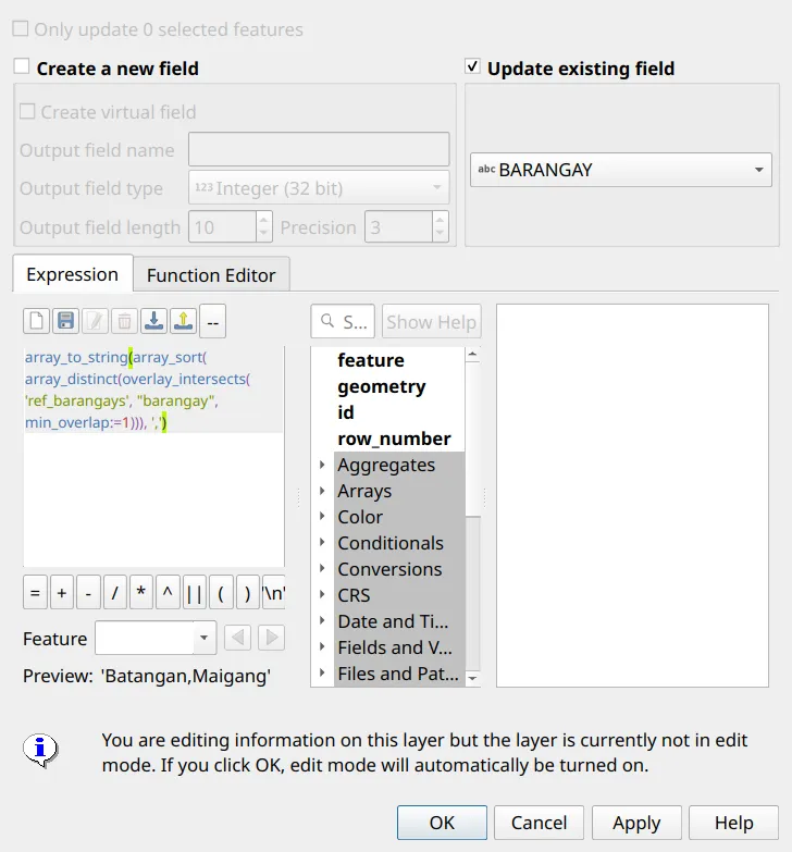
- Update MUNI_CTY and PROVINCE in the same way, using the muni_city and province fields of ref_barangays:
array_to_string(array_sort(array_distinct(overlay_intersects('ref_barangays', "muni_city", min_overlap:=1))), ',')array_to_string(array_sort(array_distinct(overlay_intersects('ref_barangays', "province", min_overlap:=1))), ',')- Fill in NAME (
'Bagong Gubat Agroforestry Cooperative'), TENURE ('Sustainable Forest Land Management Agreement'), and REGION ('IV-A'), then save your edits.

Multiple parcels
Section titled “Multiple parcels”If the application involves multiple parcels:
- put all parcels in one polygon shapefile, one feature per parcel, and
- create one point shapefile per parcel, each with its own corner numbering.
Certification and support
Join an upcoming training to take this as an instructor-led course, or contact us to arrange one for your team or organization.