
Technical descriptions and corner coordinates
Before we begin
Section titled “Before we begin”What we want to achieve
Section titled “What we want to achieve”- Number the corners of the application area consistently.
- Compute the northing and easting of every corner with Add X/Y fields, as the guide prescribes.
- Generate the technical description in the standard bearing-distance format, including the tie line.
- Export the technical description and the computed coordinates with the prescribed names.
What we have
Section titled “What we have”- area_boundary - the boundary of the sample application, with its attributes filled in
- area_corners - the empty corners shapefile with the prescribed fields
- sample_tie_point - the tie point of the sample application and its coordinates
Relevant QGIS knowledge/skills
Section titled “Relevant QGIS knowledge/skills”- Field calculator
- Expressions
- Selects and filters by attribute
- The QGIS Processing Framework
- Exporting layers from QGIS
Anatomy of a technical description
Section titled “Anatomy of a technical description”The guide requires the technical description to be presented in bearing-distance format, and the coordinates of the tie point and the description of the tie line must always be given and complete.
A technical description has three parts:
| Part | Contents | Example from the sample application |
|---|---|---|
| Lines | One row per side of the area: the line (from corner to corner), its bearing, and its distance in meters | 1-2 · S 70° 48' 03" E · 186.90 |
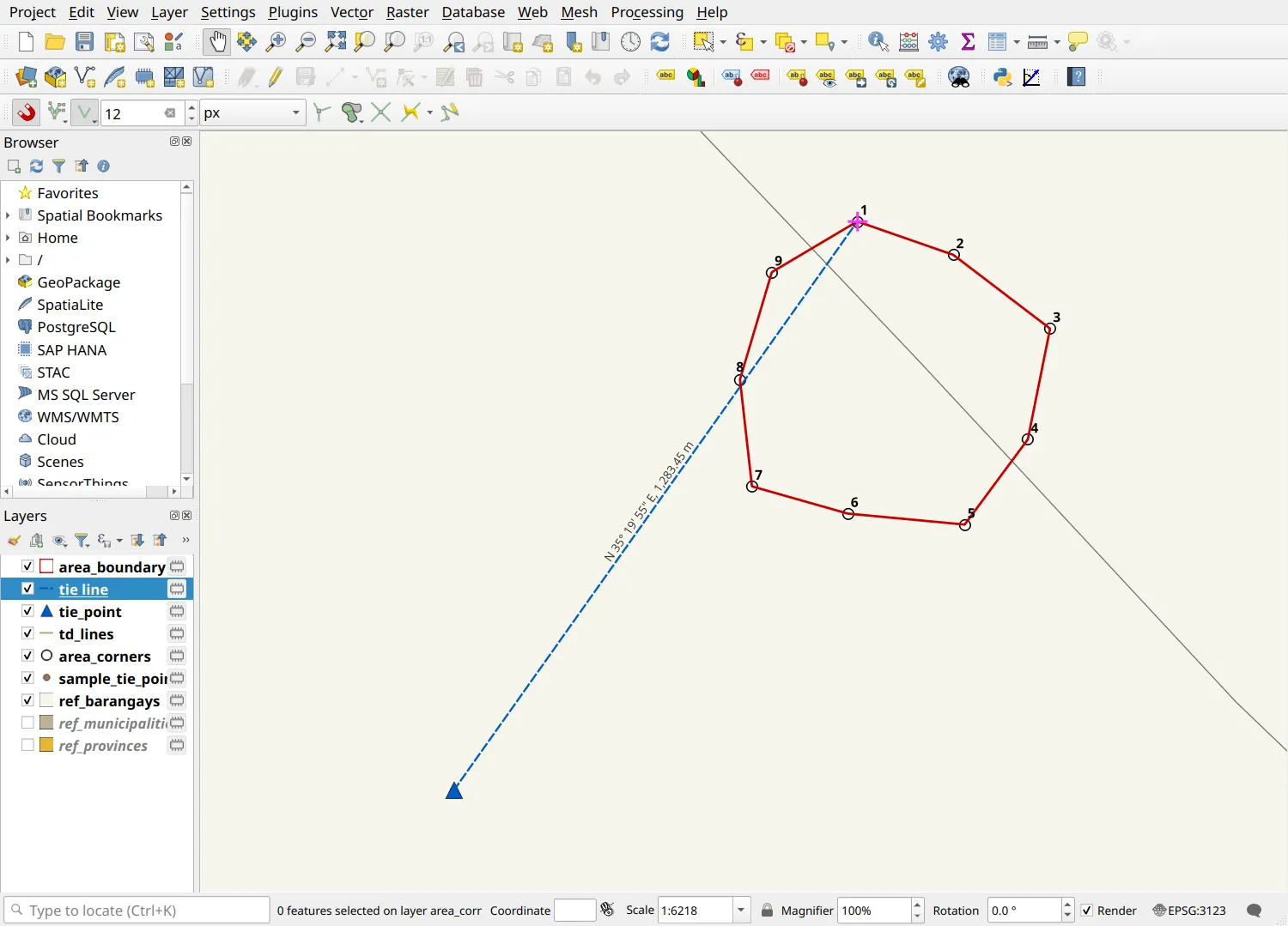
| Tie line | The bearing and distance from the tie point to corner 1 | Point 1 is N 35° 19' 55" E, 1,283.45 meters from BLLM No. 1 |
| Original coordinate of the point | The reference point’s name, easting, northing, and datum and zone | Easting 560167.218, Northing 1628537.085, PRS 1992 Philippines Zone III |
Bearings and azimuths
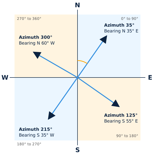
Section titled “Bearings and azimuths”An azimuth is measured clockwise from north, from 0° to 360°. A bearing is measured from north or south, toward east or west, from 0° to 90°. QGIS computes azimuths, so every bearing in this module is converted from an azimuth.
| Azimuth | Bearing |
|---|---|
| 0° to 90° | N azimuth E |
| 90° to 180° | S (180° − azimuth) E |
| 180° to 270° | S (azimuth − 180°) W |
| 270° to 360° | N (360° − azimuth) W |
Numbering the corners
Section titled “Numbering the corners”3.1. Extracting and numbering the corners
Section titled “3.1. Extracting and numbering the corners”- Run Processing Toolbox ‣ Extract vertices on area_boundary.
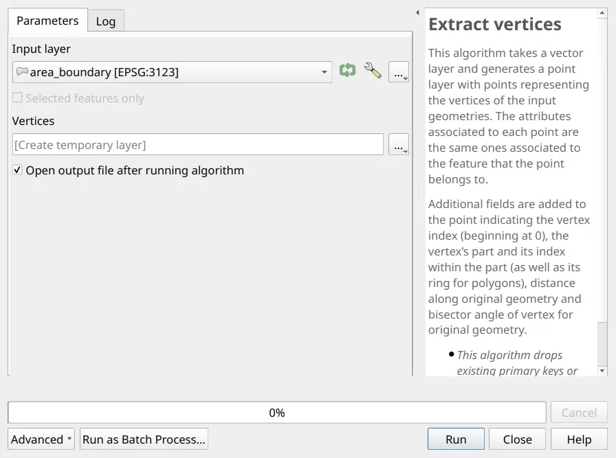
- The output has ten points for nine corners: in a closed polygon, the last vertex repeats the first. Select it with Select by Expression (
 ) and delete it:
"vertex_index" = maximum("vertex_index")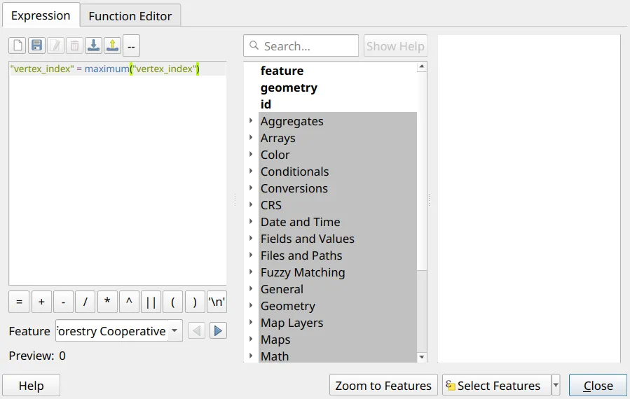
- Add T_CORNER to the vertices with the Field Calculator (
 ), as a Whole number (integer) field. A polygon plotted from a technical description, as in Exercise 2.2, starts at corner 1, so:
"vertex_index" + 1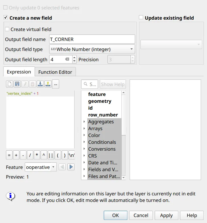
If corner 1 is another vertex (for example, a polygon digitized from a different starting point), note that vertex’s vertex_index and number the corners from it. For corner 1 at vertex index 3:
(("vertex_index" - 3 + count("vertex_index")) % count("vertex_index")) + 1- Keep the Vertices layer: the next exercise computes the corner coordinates on it and then copies the corners into area_corners.
Computing the corner coordinates
Section titled “Computing the corner coordinates”The guide says: “The preparer shall calculate the Northings and Easting (NE) coordinates of the area using the Add X, y coordinates function in GIS. The calculated NE in shapefiles should be matched to ensure the correctness of the location of the area being applied for.” In QGIS, that function is Processing Toolbox ‣ Add X/Y fields to layer.
When is Add X/Y fields safe?
Section titled “When is Add X/Y fields safe?”Add X/Y fields computes correct coordinates, but two of its defaults work against the prescribed shapefile. It is safe when:
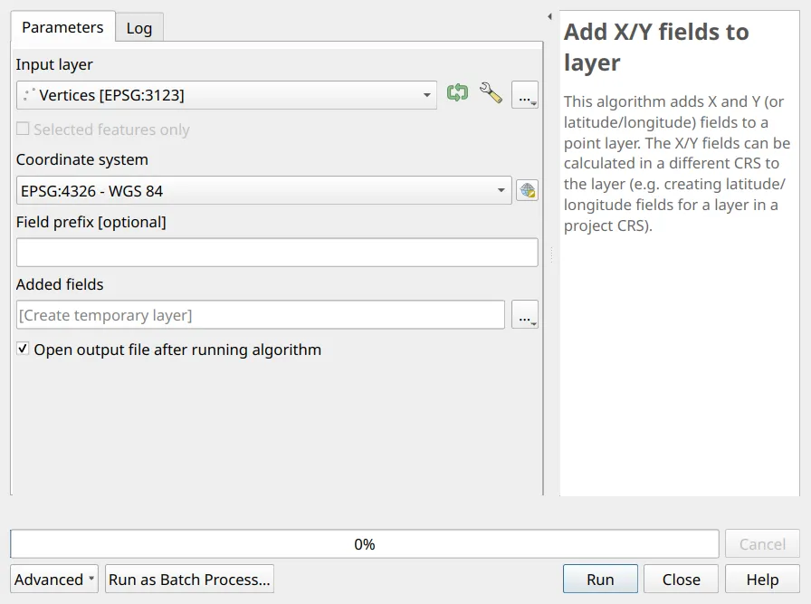
- The coordinate system is the layer’s own CRS, the datum and zone of the technical description. The tool’s default is EPSG:4326, which writes degrees: corner 1 of the sample becomes 121.567012 and 14.733692. Any other CRS is converted silently: with Luzon 1911 Zone III instead of PRS 1992 Zone III, corner 1 moves by 7.7 meters without a warning.
- It runs normally, not with Edit Features In-Place. In place, the tool stops with Destination field not found.
- Its fields stay out of the submission. The tool adds new fields instead of filling EASTINGS and NORTHINGS, and on a layer that already has the prescribed X and Y it names them x_2 and y_2. Use a prefix such as
NE_so the new fields are clearly yours, and run the tool on the vertices rather than on the prescribed shapefile. Copying the corners into the shapefile afterwards keeps only the prescribed fields. - The values are rounded. The tool keeps ten decimals; the guide’s coordinates have three.
3.2. Computing NORTHINGS and EASTINGS with Add X/Y fields
Section titled “3.2. Computing NORTHINGS and EASTINGS with Add X/Y fields”- Open Processing Toolbox ‣ Add X/Y fields to layer and choose the numbered Vertices as the input. Note the default Coordinate system:
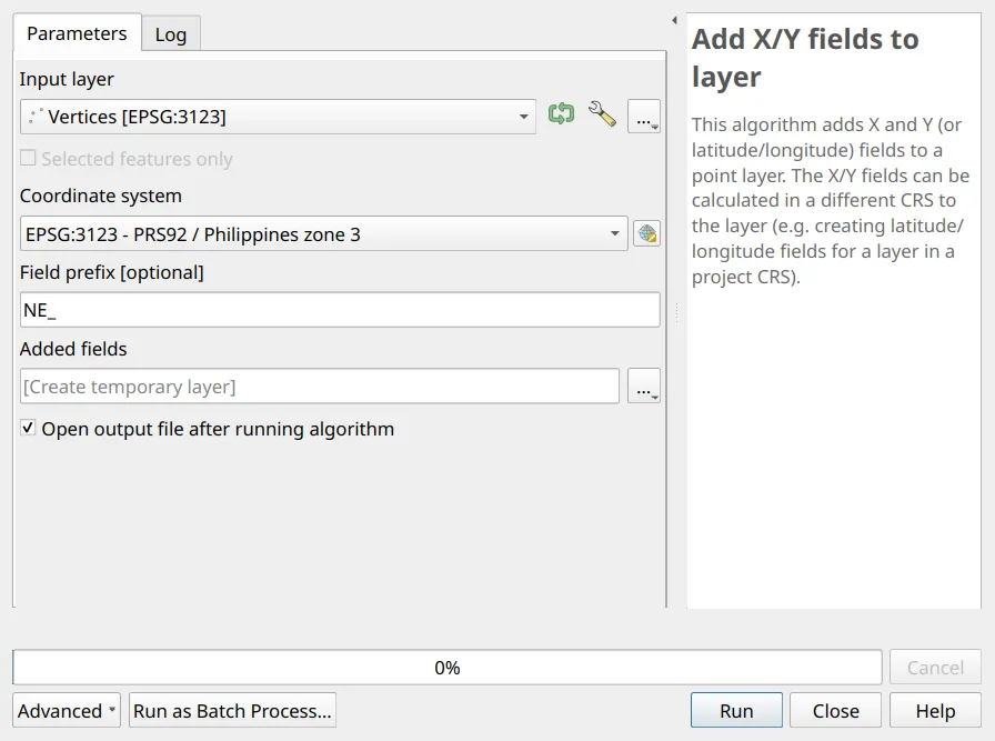
- Set the Coordinate system to EPSG:3123 - PRS92 / Philippines zone 3 (the layer’s own CRS) and the Field prefix to
NE_, then click Run.
- In the output layer (Added fields), add EASTINGS and NORTHINGS with the Field Calculator as Decimal number (real) fields of length 20 and precision 3, rounding the new fields to the millimeter:
round("NE_x", 3)round("NE_y", 3)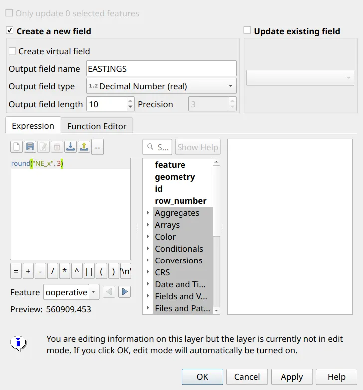
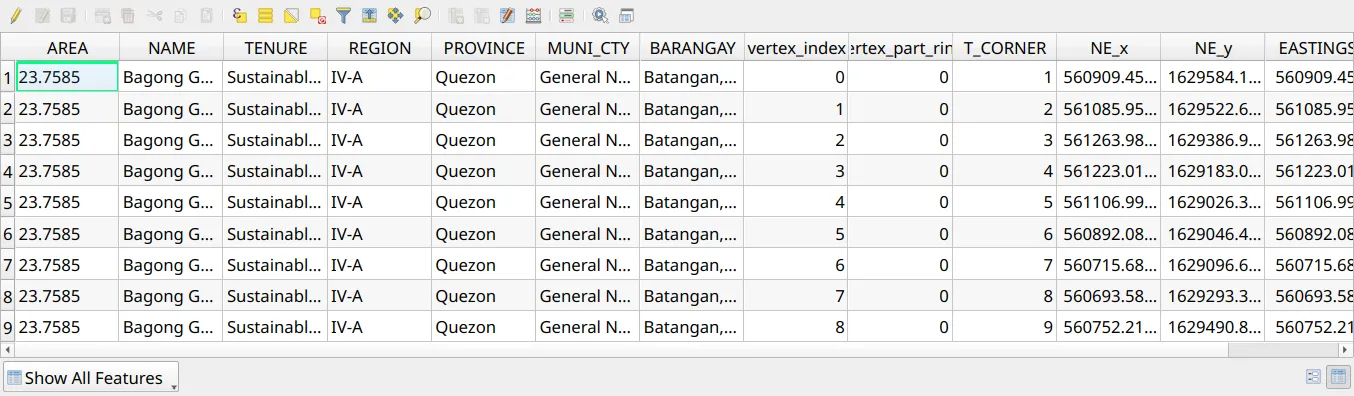
- Select all the features of Added fields, copy them (Edit ‣ Copy Features), select area_corners, toggle editing, and paste them (Edit ‣ Paste Features). QGIS fills the fields that have the same name: T_CORNER, EASTINGS, and NORTHINGS, and also NAME, TENURE, REGION, PROVINCE, MUNI_CTY, and BARANGAY, which the vertices carried over from the area boundary. NE_x, NE_y, and the other helper fields do not exist in the shapefile and are left out, and X and Y stay blank. Save your edits.
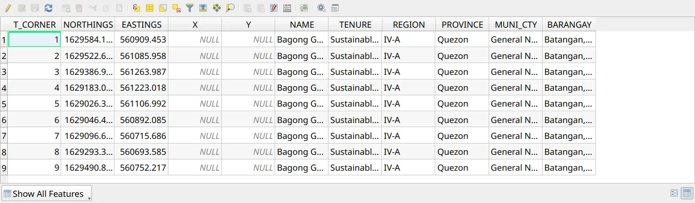
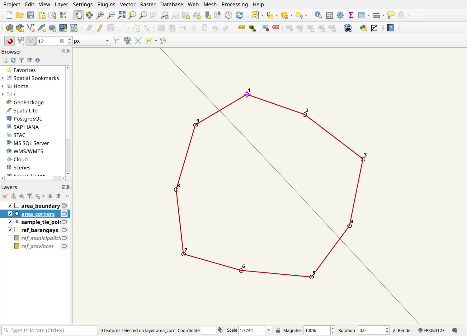
- Do the guide’s check: the computed coordinates must match the shapefile. On area_corners, Select by Expression () the corners whose NORTHINGS or EASTINGS differ from their position by more than a millimeter. No corner should be selected.
abs("EASTINGS" - x($geometry)) > 0.001 OR abs("NORTHINGS" - y($geometry)) > 0.001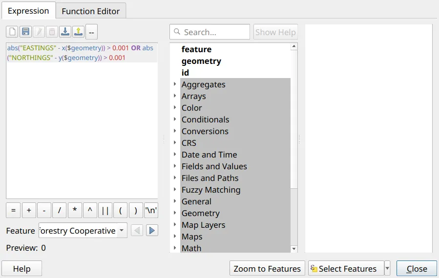
Computing bearings and distances
Section titled “Computing bearings and distances”3.3. Generating the lines of the technical description
Section titled “3.3. Generating the lines of the technical description”What we want to achieve
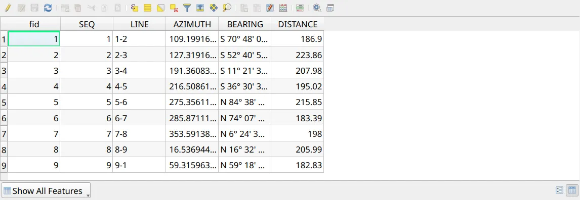
Section titled “What we want to achieve”- A table with one row per line of the technical description: the line label, bearing, and distance.
- Convert the area boundary to lines with Processing Toolbox ‣ Polygons to lines.
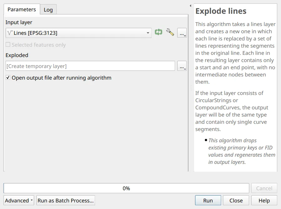
- Split the boundary into one feature per side with Processing Toolbox ‣ Explode lines.
- Save the exploded lines before adding fields: right-click the layer ‣ Make Permanent, and save it as td_lines in a GeoPackage (e.g. bnhr_qgis-sflma-mapping-outputs.gpkg).
- With the Field Calculator, add these fields to td_lines, in order:
SEQ (Whole number), the number of the corner each line starts from, used to sort the lines:
aggregate('area_corners', 'max', "T_CORNER", filter:=distance($geometry, start_point(geometry(@parent))) < 0.001)LINE (Text), the corner numbers at both ends of the line, such as 1-2:
with_variable('a', aggregate('area_corners', 'max', "T_CORNER", filter:=distance($geometry, start_point(geometry(@parent))) < 0.001),with_variable('b', aggregate('area_corners', 'max', "T_CORNER", filter:=distance($geometry, end_point(geometry(@parent))) < 0.001),@a || '-' || @b))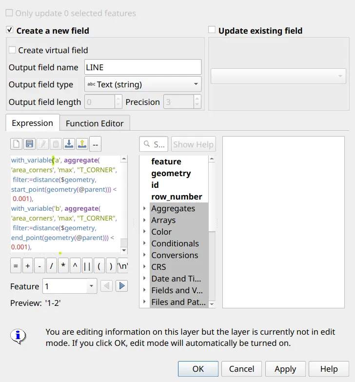
AZIMUTH (Decimal number), the grid azimuth of the line in degrees:
degrees(azimuth(start_point($geometry), end_point($geometry)))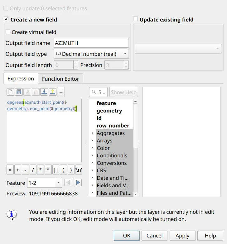
BEARING (Text), the azimuth as a quadrant bearing rounded to the second:
with_variable('az', "AZIMUTH",with_variable('q', CASE WHEN @az < 90 THEN @az WHEN @az < 180 THEN 180 - @az WHEN @az < 270 THEN @az - 180 ELSE 360 - @az END,with_variable('s', round(@q * 3600),CASE WHEN @az < 90 OR @az >= 270 THEN 'N' ELSE 'S' END|| ' ' || floor(@s / 3600) || '° '|| lpad(floor((@s % 3600) / 60), 2, '0') || ''' '|| lpad(@s % 60, 2, '0') || '" '|| CASE WHEN @az < 180 THEN 'E' ELSE 'W' END)))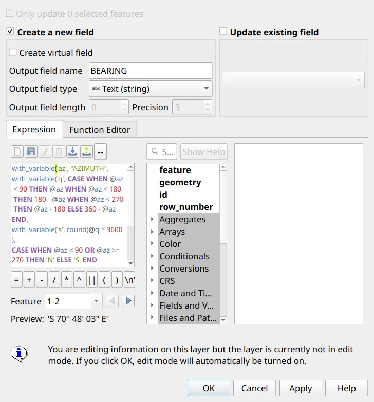
DISTANCE (Decimal number, precision 2), the grid distance in meters:
round(length($geometry), 2)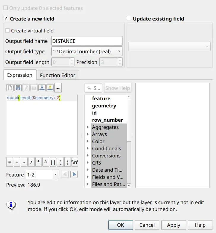
The tie line
Section titled “The tie line”3.4. Computing the tie line
Section titled “3.4. Computing the tie line”What we have
Section titled “What we have”- sample_tie_point - the reference point, with its name and coordinates
- Save sample_tie_point as tie_point in the same GeoPackage as td_lines (Export ‣ Save Features As…), so that you can add text fields to it.
- With the Field Calculator, add these fields to tie_point:
AZIMUTH (Decimal number), from the tie point to corner 1:
degrees(azimuth($geometry, geometry(get_feature('area_corners', 'T_CORNER', 1))))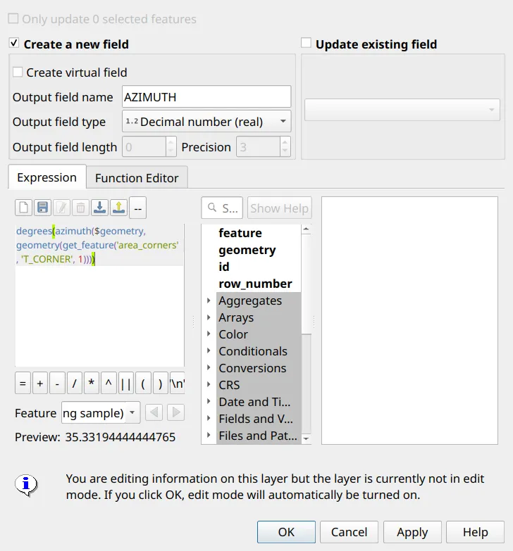
TIE_BEARING (Text): the same bearing expression as in Exercise 3.3.
TIE_DISTANCE (Decimal number, precision 2):
round(distance($geometry, geometry(get_feature('area_corners', 'T_CORNER', 1))), 2)TIE_LINE (Text), the tie line in the prescribed wording:
'Point 1 is ' || "TIE_BEARING" || ', ' || format_number("TIE_DISTANCE", 2) || ' meters from ' || "ref_point"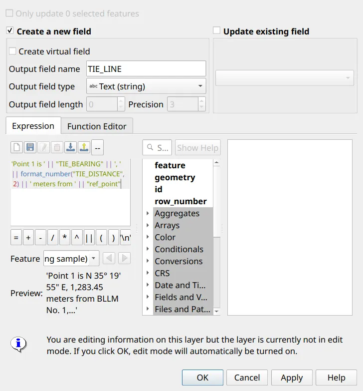
Exporting the technical description and coordinates
Section titled “Exporting the technical description and coordinates”3.5. Exporting the technical description and computed coordinates
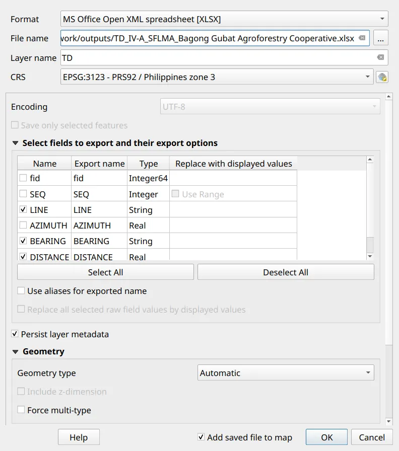
Section titled “3.5. Exporting the technical description and computed coordinates”- Put the lines in order with Processing Toolbox ‣ Order by expression, ordering td_lines by SEQ (sorting the attribute table does not change the order features are exported in). Then right-click the ordered layer ‣ Export ‣ Save Features As…:
- Format: MS Office Open XML spreadsheet [XLSX]
- File name:
TD_IV-A_SFLMA_Bagong Gubat Agroforestry Cooperative.xlsx - Layer name: TD (this becomes the sheet name)
- Under Select fields to export, keep only LINE, BEARING, and DISTANCE
- Export tie_point to the same file with the layer name Tie line, keeping ref_point, easting, northing, datum, TIE_BEARING, and TIE_DISTANCE. QGIS asks whether to add a new layer to the existing file: choose to add it, and the spreadsheet gets a second sheet.
- Order area_corners by T_CORNER in the same way and export it as Comma Separated Value [CSV], keeping T_CORNER, NORTHINGS, and EASTINGS, named
TD_IV-A_SFLMA_Bagong Gubat Agroforestry Cooperative.csv. - For multiple parcels, export each parcel’s technical description and coordinates to a separate sheet of the same spreadsheet.
Certification and support
Join an upcoming training to take this as an instructor-led course, or contact us to arrange one for your team or organization.